We have been promising to upload instructions for how to build the sensor for detecting white or black surfaces. This post represents the first go at describing this process. To begin, here is the outline of the sensor circuit that we need to build.
The key to this circuit is the RPR220 reflective photosensor, from Rohn Semiconductor. This sensor is made up of an infrared (IR) diode that shines IR radiation on a surface, and a photo-transistor that passes varying amounts of electrical current depending on how much of the emitted IR radiation is reflected back from the surface. If the surface is black then the amount of reflected IR is low. If the surface is white, then the amount of reflected IR is much higher snf the transistor conducts. This sensor circuit produces a high voltage (near 3 volts) if the sensor is placed a few mm above a white surface, pointing directly down at it. In a simular fashion the circuit produces a low voltage (just above 0 volts) if the sensor is held the same distance above a black surface. This sensor circuit can therefore be used to detect when a slambot has reached the edge of a table with a black surface in the centre and a white region near the outer edge.
This next image shows the parts you will need to build the sensor circuit
– one RPR220 reflective photosensor
– one 10 kOhm resistor (brown, black orange – gold)
– one 220 Ohm resistor (red, red, brown – gold)
– one 4-piece terminal strip
– 50mm lengths of red(3V) black(0v) and blue (sensor o/p signal) single strand wire.
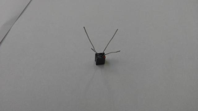
To start, position the RPR220 so that the pins are pointing towards you with the bevelled corner (highlighted with a faint red line in the image) in the bottom right hand corner.
With the RPR220 still in the position from the last step with pins facing you and bevel in bottom right corner, use a pliers to wind the ends of the two topmost pins (pins 1 and 3) of the RPR220 together in a tight spiral.
Again using a pliers twist the RPR220 pin and resistor lead together to tie the 10kOhm resistor (brown, black orange – gold) to the bottom right pin.
- Now add the second 220Ohm resistor to the remaining RPR220 pin. In the same way twist the ends of the two resistors together.
- The circuit now needs to be reshaped to insert into the terminal strip.
Using a small flathead screwdriver fix each of the four wound pairs of wire into the four terminals on one side of he terminal block. The red cable is then connected in to the terminal opposite the two wound-together leads from the RPR220.
The black cable is connected to the terminal opposite the two wound-together resistors.
The blue cable is connected opposite the remaining end of the 10k resistor (brown, black, orange, gold). The circuit is now ready for testing.


What Voltage or Battery size are you using to connect the sensor with?
LikeLike
Hi Syed,
This was designed for a 3V circuit, but it should work fine at 5V also. In the diagram at the top, connect the red to 3V (or 5V) and the black to 0V. The blue wire is the output. It should be high (by which I mean close to 3V or 5V, depending which you’re using) when the sensor sees white and low (by which I mean close to 0V) when it sees black.
The entire sensor module will only draw a handful of mA current (less than 10mA), so it should be easy to power it from a wide variety of 3-5V voltage sources.
Ted
LikeLike