
Assembly instructions laser cut Slambot chassis for attendees at DIT CAO open day
We recently took delivery an awesome new resource that promises to revolutionise future Roboslam workshops – a laser cutter! Eagle-eyed site visitors will note that a number of laser cut robots have already featured in previous Roboslam events, for the Dublin Maker Faire and again for the Kinsale Arts Festival gig. These experiments were successful so we applied for sponsorship to purchase a system of our own. This post documents the first public outing of laser cut parts from our brand new Epilog Laser cutter.
As an honours engineering degree student in DIT, you would have an opportunity to design a robot chassis of your own as part of our Robo Sumo module for 1st engineers. This task should give you a taste of that activity.
The chassis parts for the robot are shown below.
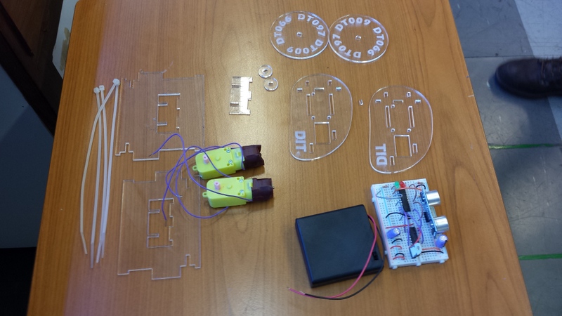
Laser cut parts
In order to fix the motors to the two side plates, first ensure that the motor axle is pointing away from side plate (DIT writing on outside of side plate and insulating tape on motor fitting into the cutout rectangle in the side plate). Then loop the cable tie through both through holes on motor and back through side plate.

… and then pull the cable through all the loops connect the head of the cable tie and tighten – but making sure to keep the head of the cable tiw on the inside of the side plate, and half way between the two fixing holes.

then snip the excess cable near the head of cable tie.

Now slide the front pillars into place…
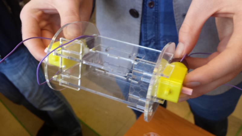
Pass a cable tie across the width of the robot through the two holes provided at the back of the motors.

Place the head of a second cable tie on the tail of the threaded cable tie and pull tight to hold chassis together. Then trim the excess cable with a snips.

Now attach the wheels. and reconnect the cables for motors and battery.
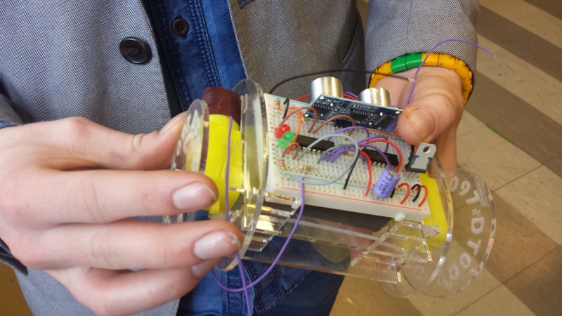
That’s it!


Are the design files available to share, if so how and where?
LikeLike
Hi Rando,
I drew the design in Inkscape, then exported to PDF to send to the laser cutter (from Adobe Reader). I’ve just shared the Inkscape SVG and the PDF version on my Google Drive. You can download them from the following links:
If you want to edit the design, for example to change the engraving, you can probably open the SVG file in other vector drawing programs, but if you want to use Inkscape it’s free to download and there are some great tutorials on YouTube, as well as in the help menu.
Ted
LikeLike
Ted,
Thanks so much!
R.
LikeLike
You’re welcome!
Ted
LikeLike
Quite an adventure learning Inkscape yesterday, grateful to finally find the outline button.
I’m off to my local Maker Group tomorrow to experiment with laser cutting some parts, wondering if there is some scaling I need to apply to make them a little larger than what prints out of my laser printer? I notice from the photographs, that the print out (PDF) is not in keeping with the size of the plates in relation to the bread board, which I have several and can serve as point of reference as to (relative) size …
Anyway, square one on doing this, there is quite a bit of expertise in the group regarding these matters.
LikeLike
Hi Rando,
A couple of useful tips for using Inkscape to do laser cutting designs:
1. Go into the “Document Properties” dialog box (either through the File menu or by pressing Ctrl + Shift + D) and set the “Default units” to mm.
2. If you plan to use the grid, you can also set the grid spacing to something convenient in mm using another tab of the same dialog box.
3. I draw most of the shapes for laser cutting using the Line and Bezier tool (either click the button in the toolbar or press Shift + F6 to select this tool). I draw out the shape of each piece very roughly near the point 0,0 on the canvas. I then press F2 to edit the nodes in the path and use the align tool “Ctrl + Shift + A” to line up the nodes that should be lined up (e.g vertical and horizontal edges). Finally, I select nodes either one at a time or in groups and use the edit boxes at the top of the canvas to set the node coordinates by typing them in. This way, it’s really easy to get all the coordinates exactly as you want them in mm.
4. In the Document properties, I normally set the page size to the size of the material I’ll be cutting in the laser cutter. Then, when I have the drawing done, I save a copy as “PDF” exporting the page area as the PDF. I normally open it in Abode Reader to do the actual laser cutting.
Hope that helps!
Ted
LikeLike
Ted,
Thanks for the advice, I’m sure it will prove invaluable. Here’s a PDF with embedded dimensions for the parts. Do the dimensions look correct?
https://drive.google.com/file/d/0B75yepgXDk6rOVdkZVFtakZ1TmM/view?usp=sharing
Can’t say enough good things about how your software side is handled. I love the cut and paste simplicity.
Can you discuss why you went with the MSP430 TI-launchpad ecosystem vs. the omnipresent Arduino? Off hand, I’m thinking that you wanted to avoid the chicken and egg problem of what/who/when burns the boot-loader, etc., but I’d like to hear from you, what your reasoning was…
LikeLike
Hi Rando,
Yes, those dimensions look the same as mine. 2.95″ is very close to 75mm and 4.33″ is very close to 110mm.
Our decision to use MSP430 was based on a number of factors:
Firstly, we use the MSP430 a lot for undergraduate teaching here in the School of Electrical and Electronic Engineering at the Dublin Institute of Technology. One of the main reasons that we use it so much is that we can buy a Launchpad with a couple of chips for less than 10 euro. We use PIC microcontrollers too, but it’s much more expensive to get up and running with a USB programmer (about 40 euro). We use lots of other development boards too (Arduino, Nucleo, ARM, etc), but I think MSP430 is the one we use the most so we basically know it inside out.
The MSP430 is a good platform for learning about microprocessors at the bare metal level (or close to it). Compared to some other platforms, the documentation for the MSP430s is relatively easy to get to grips with (not that it’s trivial of course). The architecture is relatively easy to get familiar with. Students can begin to program at the register level in C without having to learn too much. This is less of a concern in our RoboSlam workshops, where we really just want to give participants a flavour of programming / electronics / robotics and how people actually design and build things that move. However, some participants do gain an insight into what’s happening at the register level, which would all be hidden from them with (for example) Arduino.
At least up until now, we haven’t had any difficulty sourcing MSP430s (G2452 and G2553) in dual inline (DIL) packages which allows students to build a circuit from scratch on a breadboard. Unfortuntely, many microcontrollers and other ICs are now only widely available in surface mount packages, which is very awkward for breadboard work.
We constantly review what we use in RoboSlam and two Arduino related things loom large on our radar: The first is Energia, which is a port of the Arduino development environment to MSP430. It seems to work great across multiple platforms (Windows / Mac) and might suit some participants better, but depending how it’s used it can hide some of the register level stuff, which it’s good for (some) participants to be exposed to. The second thing is the influx of ultra low-cost Arduino nano clones from China. We can get these for the equivalent of about 2 euro on aliexpress.com now. They plug into a breadboard and don’t require a separate programming board – you just need a USB cable to plug into the PC. They come with a bootloader installed, so they should be just plug and play, but I have had a few driver issues with them on some computers, which has not tended to be a problem with the MSP430 LaunchPad (unless you want to use the UART).
Ted
LikeLike
Ted,
Thanks so, so much for your well considered comments.
Here at IU I’ve run into many similar issues, just a little FIY from my hard won experience.
1. The TI driver that supports the back channel serial port, is a little flaky under linux, and I had some issues with using it until just recently, with Ubuntu 14.10 where they finally seemed to resolved. Energia similarly had some Linux issues, that I hope are fixed as well.
Under windows Energia has always run great, and especially noteworthy is that Energia projects will now export to TI’s CCS, and provides a smooth “learning trajectory” between the simple Energia examples, and the more formal, step by step, “de-buggable” C code.
I like the idea of taking the students from the convenience of the wiring library, to the deeper understanding of what’s going on inside the micro-controller across one continuous learning experience. Pity they had to raise the price of the basic Launchpad from 5$ to 12$, but still a great value considering.
2. Regarding the CH340G chip in the Nano clone, I’ve been lucky on Windows 8.x as the drivers auto-magically load (which is unusual, Windows 8 is quite the hassle), same with Linux, and I think there are good drivers for Mac OS posted on line. I actually bought some USB2TLL converters based on this chip for .80$ yesterday, and since in education the cheaper the better, I have to look at how I would incorporate them somehow in my projects.
3. Here’s a link to review a PCB for the MSP430G, with integrated voltage regulator that is very bread board friendly, These are inexpensive, I can send you a few if interested, and make simple to order online in future.
https://drive.google.com/file/d/0B75yepgXDk6rM3ZWemo3ZTdOU2c/view?usp=sharing
I guess great minds run together, Energia and the Chinese Nano were precisely what I want to try first, when I get the acrylic parts for my robot next week. I hit the local maker group meeting last night, and “laser printing” the parts locally is a done deal, as soon as I get a little training on the cutter.
What would be the preferred method for us to talk sometime? I’d love to come to Ireland and take a look at your setup this summer, and take a little/observe workshop training, great input for my dissertation.
Randy
LikeLike
Pingback: RoboSlam @ Dublin Maker – only two days away! | RoboSlam